In machine vision, good lighting does more than simply illuminate a part. It helps the camera see the details that matter, with enough contrast to make inspection reliable and repeatable. This is exactly why geometry plays such an important role. The position of the light, the angle of the camera, and the way the part sits in the setup all affect how the surface will appear in the image. A small change in this relationship can make the difference between a clear inspection result and an image filled with glare, shadows, or missing details. Understanding geometry makes it easier to choose the right lighting approach for each application.
System Geometry
System geometry is the overall arrangement of the inspection setup. It describes where the camera is placed, where the light is positioned, and how the part sits in relation to both. This matters because even before light reaches the surface, the physical setup already influences what the camera will be able to see clearly and what may become harder to inspect.
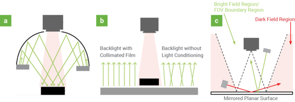
a – Diffuse dome lighting in an on-axis system geometry, b – Backlighting showing collimation on the left and standard backlighting, c – Off-axis front lighting in bright-field and dark-field configurations.
Light Ray Geometry
Light ray geometry is about what the light does after it leaves the source. In other words, it explains how the light reaches the surface, how it bounces off that surface, and whether it goes back to the camera or away from it. This is important because the way light reflects can either reveal useful details, such as texture or markings, or create glare that hides them.
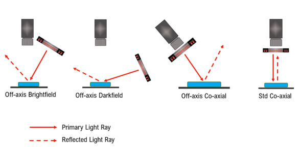
System geometry examples illustrating the relationship between camera, light, and reflected light in different lighting setups.
System Geometry vs. Light Ray Geometry
The difference between the two is that system geometry describes the setup itself, while light ray geometry describes the result that setup creates. One is about placement, and the other is about behavior. When you change the position of the light or the camera, you are changing the system geometry, but what really matters in the final image is how that change affects the path of the light and the way the part appears to the camera.
On-axis System Geometry
From a system-geometry perspective, on-axis lighting describes arrangements in which the illuminator is centred around the camera’s optical axis. This broader category may include dome, tunnel, flat diffuse, ring, and true coaxial lights. However, their light-ray geometries differ, as being centred around the camera does not necessarily mean that the individual rays travel parallel to the optical axis. True coaxial illumination, which uses a beam splitter to direct light along the camera’s optical path, is therefore treated as a specific technique within this broader system geometry.
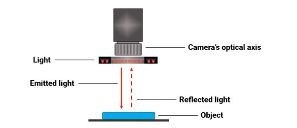
Representation of an on-axis system geometry: the illuminator is centred around the camera’s optical axis, although the direction of the individual light rays may vary depending on the lighting technique.
Dome Lighting
Dome lighting is similar to the light on a cloudy day. This happens because clouds act like a large natural diffuser. Sunlight passes through this layer and spreads in all directions. Instead of coming from a single point, it comes from multiple angles at the same time. The result is soft, even lighting, with almost no shadows and much more controlled reflections. Dome light reproduces exactly this behavior within an industrial environment. Although a dome light is typically mounted concentrically around the camera lens, its illumination is not true coaxial illumination. Instead, it reaches the object from a broad range of directions and angles.
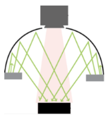
Diffuse dome lighting in an on-axis system geometry
Proximity is essential because the part needs to be practically surrounded by diffuse light. When the dome is far away, it loses this omnidirectional effect and starts to behave like a common light source, reducing its efficiency. Diffuse dome lights are especially efficient for illuminating curved and highly reflective surfaces, such as those often found in the automotive industry, for example.
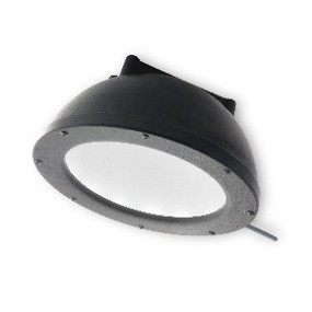
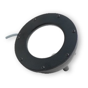
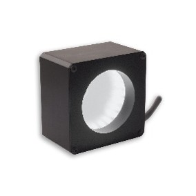
If you would like to know more details about dome lights, check out some of Advanced Illumination’s products:
Flat Dome Lighting
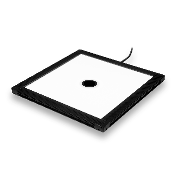
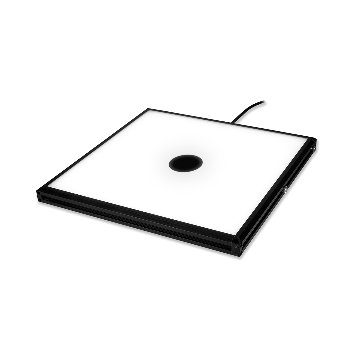
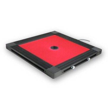
Flat diffuse lights can be understood as an intermediate solution between traditional dome lighting and true coaxial lighting. They use a flat, diffuse emitting surface to direct light toward the object, without relying on the internal reflections used by a traditional dome. From a light-ray geometry perspective, they produce more off-axis rays than a true coaxial illuminator, but fewer than a dome light.
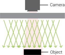
Flat diffuse light function diagram: the light is directed towards the object and contains more off-axis ray contribution than a true coaxial illuminator, but less than a dome light. This makes it less suitable than a dome for inspecting highly curved, reflective surfaces.
In practice, this brings an important advantage, because since the light is direct, it is possible to work with greater distances and illuminate larger areas, something that is not feasible with traditional dome lights, which need to be very close to the part, making this solution especially suitable for applications such as code reading on flat surfaces, PCB inspection, components with moderate geometry, and scenarios that require good uniformity over larger fields of view.
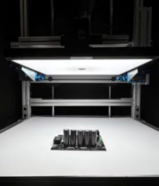
FD1212 with a WD of 220mm
See below and explore Advanced Illumination’s Flat Dome Lighting solutions in more detail:
True Coaxial Lighting:
A true coaxial light uses a beam splitter to direct illumination along the same optical path the camera uses to observe the object. After reaching the surface, the reflected light returns through this shared path to the sensor, providing highly controlled illumination and reflection capture. Unlike dome, flat diffuse, and ring lights, true coaxial lighting aligns the illumination path directly with the camera’s optical axis.

This behavior causes flat and highly reflective surfaces to appear bright and uniform, while variations such as engravings, textures, or defects deflect the light and become darker. For this reason, this lighting is widely used in the inspection of polished metals, the reading of codes or laser markings, and the detection of imperfections on flat surfaces.
If you would like to go deeper, check out some Advanced Illumination coaxial light models:
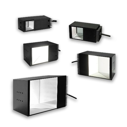
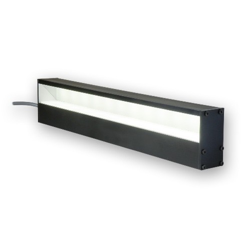
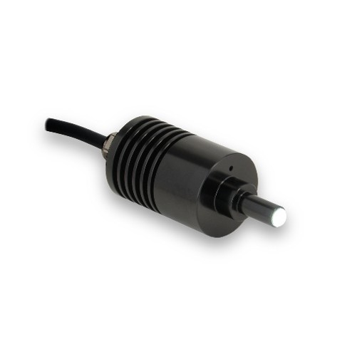
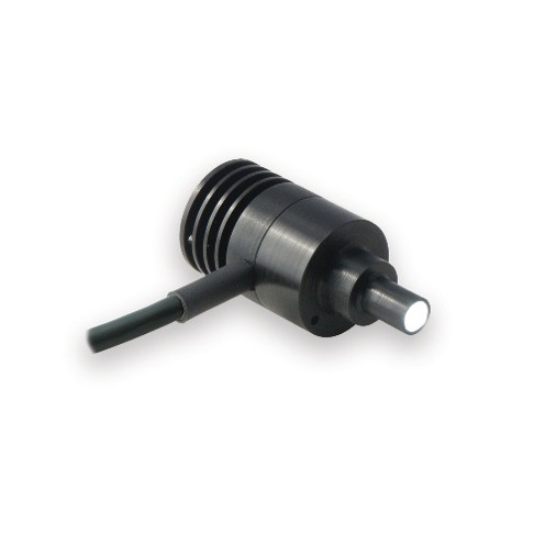
Ring Lights
One of the most popular choices in machine vision applications, ring lights are mounted concentrically around the camera lens, creating an on-axis arrangement from a system-geometry perspective. However, because the emitting elements are positioned around rather than directly on the optical axis, the individual rays generally reach the object at an angle. The effective illumination angle depends on the ring diameter, LED optics, and working distance. Shorter working distances generally produce a more pronounced off-axis effect, while longer working distances make the illumination more nearly axial.
Ring Lights stand out for their flexibility, since they can be applied in different lighting geometries, working distances, and inspection types. They are simple solutions to install in your system, in addition to offering high light intensity and different angle configurations, allowing you to adjust the way the light interacts with the object and better highlight its three-dimensional characteristics. Features such as diffusers help distribute the light more evenly, while polarizing filters can be used to reduce reflections and hotspots. Ring lights can be used in Bright Field when positioned at more direct angles, providing uniform illumination for general inspections, especially on matte surfaces. In Dark Field, on the other hand, they are applied at low angles, where only defects such as scratches, edges, or irregularities reflect light to the camera, making detection easier.
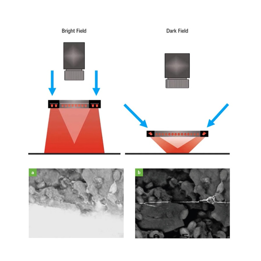
A peanut brittle bag under a bright field ring light (a) and under a dark field ring light (b), which very visibly shows the seam and underlying contents.
To understand which ring light configuration can best meet your inspection needs, get to know Advanced Illumination’s solutions:

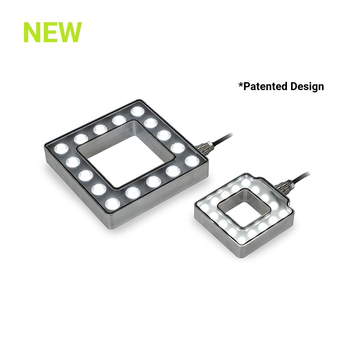
DF196 – MicroBrite™ Direct Dark Field Series / RL322 – UltraSeal™ Ring Light Series.
Backlights
Backlights are light sources positioned behind the part so that the camera sees the object as a dark silhouette against a bright background. This geometry creates immediate contrast and makes it easier to identify contours, edges, holes, openings, and the general shape of the part, making it very useful when the goal is to measure, verify presence or absence, confirm position, orientation, or detect defects visible through light transmission.
In practice, backlights are widely used in dimensional inspections, hole detection, liquid level control, analysis of translucent materials, and inspection of glass or plastic for defects. Although the backlight and camera may be aligned along the same system axis, backlighting is classified separately because the image is formed primarily through transmitted light or silhouette contrast rather than reflected front illumination.
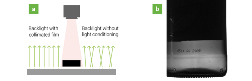
a – Back Lighting function diagram, b – Amber bottle imaged with a red 660 nm back light; note the lot code is clearly highlighted, but the light does not penetrate the label (left side of image)
For high-precision measurements, they can be combined with monochromatic light and collimation film, which reduces light dispersion and generates sharper edges, improving measurement precision. In high-speed applications, such as inspection of plastic films, fabrics, or materials in continuous motion, linear backlight versions are used to provide the necessary intensity in systems with line-scan cameras.
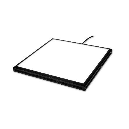
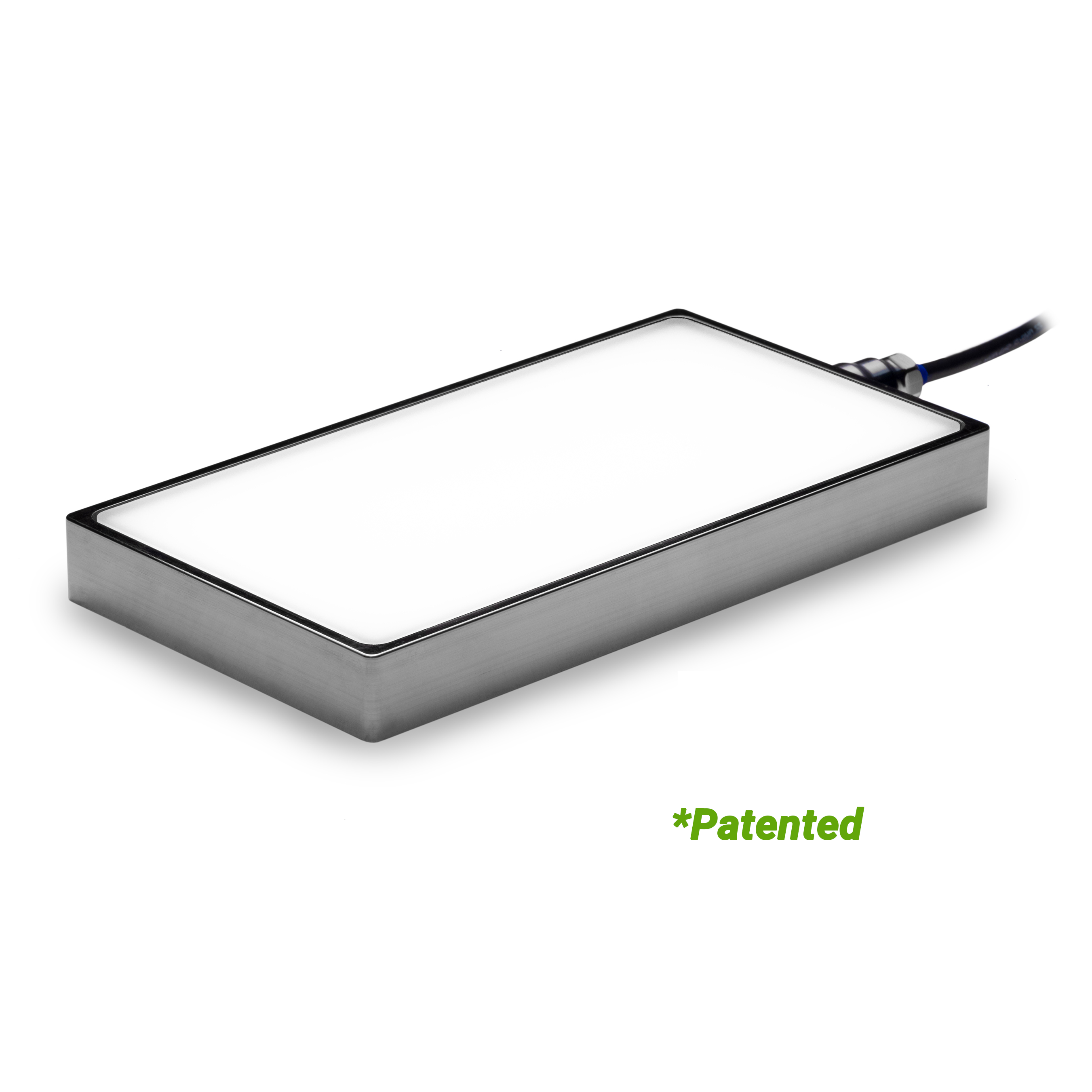
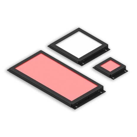
Advanced Illumination offers different backlight solutions to meet various geometries, working distances, and inspection conditions:
Off-axis Front Lighting
Off-axis front lighting describes arrangements in which the light rays reach the object at an angle relative to the camera’s optical axis. The camera typically views the part from the front, while the illumination reaches it from the side or from an inclined angle. This geometry changes the way reflections return to the camera and is therefore useful for controlling glare, highlighting surface details, or revealing defects that may not appear clearly under more axial illumination. This type of configuration can be created using ring lights, bar lights, or spot lights, depending on the illumination area, working distance, optical design, and feature to be highlighted.
In practice, off-axis front lighting can work as partial brightfield, when the light still directly illuminates the part and helps with general inspections, or as darkfield, when the light arrives at lower angles and highlights scratches, edges, reliefs, particles, or cracks.
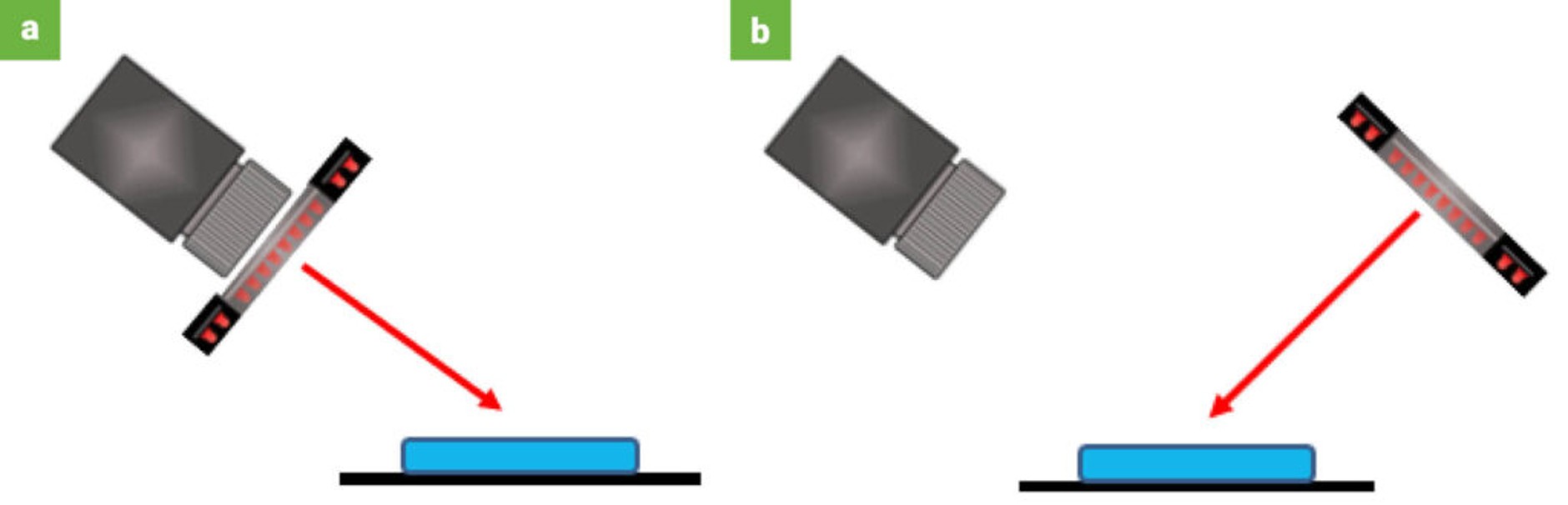
a – A camera and illuminator maintained in a coaxial system arrangement but positioned off-axis relative to the surface, helping minimise specular reflection; b – An off-axis, non-coaxial arrangement designed to capture reflections from specific surface features.
Partial Bright Field
Partial bright field is a directional lighting technique in which light reaches the part from one side or from a specific angle, rather than surrounding the entire surface with diffuse illumination. It is often used to highlight surface texture, shape, and fine details, because the direction of the light helps create contrast in the image.
Dark Field
Dark field is a lighting technique where light reaches the surface at a very low angle, helping small defects and surface details stand out more clearly. A simple way to picture it is car headlights at night, when the road may still look dark, but bumps, cracks, or small objects become much easier to notice because the light is skimming across the surface.
Ring Lights
Low-angle ring lights can be used in dark-field configurations to reduce glare from the main surface and make small surface features easier to detect. Their effectiveness depends on the angle at which the rays reach the object, which is influenced by the ring design, optics, diameter, and working distance. Scratches, edges, and raised or recessed marks can then scatter light back towards the camera while the surrounding surface remains relatively dark.
Spot Lights
Spot lights are useful when you want to focus the light on one specific area and have more control over the image. They work well when only one small feature matters and you want to make that area stand out more clearly from the rest of the part.
Bar Lights (Linear Array)
Bar lights are a good choice when you need to light a wider area and still control the direction of the light. When placed at a low angle, they can help reveal surface texture, dents, scratches, or other small defects that are hard to see with more even lighting.
On-axis vs Off-axis
On-axis and off-axis lighting serve different purposes in machine vision. On-axis lighting is usually a good choice when the goal is to create a more direct, even, and controlled image, especially on flat surfaces or in inspections that require visual consistency. Off-axis lighting, on the other hand, is more useful when reflections need to be controlled or when surface details such as texture, scratches, edges, or defects need to stand out more clearly. In practice, the best choice depends on the part, the surface, and the feature that needs to be seen with the right level of contrast.
Lighting Technique Application Fields
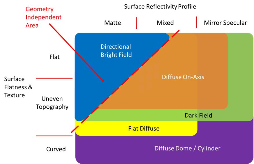
Lighting Technique Application Fields shows that not every lighting method works the same way for every part. Some surfaces are easier to inspect because they are flat and matte, while others are more difficult because they are shiny, curved, or textured. That is why the best lighting choice depends on the surface and on what needs to stand out in the image.
In the diagram, the axes represent how simple or challenging the surface is. The red diagonal line helps show the point where lighting geometry starts to matter more. The area marked as Geometry Independent Area represents the range where lighting is usually more flexible, because simpler surfaces can often be inspected successfully with different lighting techniques.
Need help finding a light with the perfect geometry for your application?
Click the link below to speak with our application experts.