Surfaces prone to uneven reflectivity are often challenging to inspect – particularly with bright-field point sources commonly used in machine vision systems. To achieve more uniform contrast over such surfaces, one solution is to apply diffuse lighting techniques.
Types of Diffuse Lighting
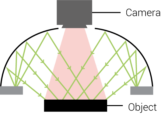
As discussed in our previous Lighting Education Blog Post, diffuse lighting in machine vision applications may be classified as full bright field illumination as opposed to partial, or directional bright field lighting. The underlying concept behind full bright field illumination, defined as illumination with a larger “solid angle”, is that light is sourced from a large area and is incident on the object surface from multiple angles (Figure 1A).

Figure 1A
Multi-Directional
Bright Field Light

Multi-Directional
Bright Field Example:
Diffuse Dome Light

Figure 1B
Partial or Directional
Bright Field Source

Partial or Directional
Bright Field Example:
Spot Light

Figure 1C
Large Solid Angle Source

Large Solid Angle Example:
Coaxial Light
Specifically, as illustrated in Fig 1A, a Diffuse Dome Light illuminates from nearly an entire hemisphere; hence it is described as having a relatively larger “solid angle” than the directional Spot Light depicted in Figure 1B.
While the Diffuse Dome Light is very effective on specular, curved, and topographic surfaces, and the Coaxial Light is effective for specular, flat, and angled surfaces of varying heights, both techniques have very specific application criteria that can present a challenge under some lighting circumstances.
Tips for Implementing Diffuse Lighting
To maintain sufficient incident light intensity, uniformity, and angular distribution, Diffuse Lights are best placed close to the intended inspection surface. This is particularly crucial for the Diffuse Dome Light for two reasons:
1) light incident on an object surface is indirect and thus less intense in general, and
2) to maintain a high solid angle for even light distribution over curved or topographic surfaces, the low angle component from the dome interior must also be incident on the surface.
It’s not difficult to imagine that a high solid angle light can become an increasingly lower solid angle and less intense light (inverse square rule) as the working distance is increased, effectively turning it into a more directional point source!
It’s also important to pair the lens focal length correctly in order to prevent vignetting, or “port-holing” – which is particularly true of the Diffuse Dome Light.
Solutions from Advanced illumination
Advanced illumination offers a diffuse source to address the application shortcomings of other diffuse, bright field lights: the FX0808 Flat Diffuse Light and FD0808 Back-lit Flat Diffuse Light. These Flat Diffuse Lights are a highly diffuse source with a viewing port in the center, allowing it to be used as front, or projection light (Figure 2).
Let’s view images from samples that illustrate the advantages of applying the Flat Diffuse Light versus other diffuse lights, including a Diffuse Dome Light and a Square Coaxial Light.

Figure 2
FX0808 Flat Diffuse Light
Inspecting PCBs with Flat Diffuse Lights
PCBs can be challenging to illuminate correctly, particularly those with large or odd-shaped components, like capacitors or heat sinks. Figures 3A-3D illustrate the differences among the three diffuse lighting options: dome, flat, and coaxial.
We see that the Diffuse Dome Light and Flat Diffuse Light work equally well for relatively small areas of the PCB (Figures 3A & 3B). In comparison, the large Diffuse Dome is less effective than the Flat Diffuse Light on larger fields-of-view, primarily because the dome has to be oversized by at least 50% of the intended field-of-view size (Figures 3C & 3D).
Figure 4 illustrates the limited size application of the 2”x2” Square Coaxial Light, where large size and set working distance are critical.

Figure 3A
DL097 Red Diffuse Dome Light

Figure 3B
FX0808 Red Flat Diffuse Light

Figure 3C
DL097 Diffuse Dome
Long Working Distance

Figure 3D
FX0808 Flat Diffuse Light
Long Working Distance

Figure 4
DL225-050 Red Square Coaxial Light
Inspecting Medical Sample Wells
Another typically challenging part to illuminate effectively is the biomedical culture or sample titer tray. These parts are often presented on a tray with a matrix of regularly spaced wells of varying size and depth. In this particular example, the wells are relatively small (5 mm wide) and shallow (3 mm deep), and spaced at approximately 8 mm in X and Y. Additionally, each well has a laser-etched 2-D matrix code that must be read and verified by a vision system as part of an FDA-requirement for sample correlation and tracking history.
For illustration purposes, we can see the 2-D matrix code in close-up views (See Figures 5A–5D). A 2” (50 mm) working distance is necessary for the code to be read and verified with a standard resolution CCD camera, while also being typical of the working distances required for effective diffuse and coaxial source lighting.
We also see that this short working distance contributes to an effective lighting geometry. However, this is not an efficient sampling strategy, as the 75 x 125 mm tray would require multiple X & Y traverses to inspect the entire tray.

Figure 5A
RL1424 Ring Light

Figure 5B
DL225-050 Coaxial Light

Figure 5C
DL2230 Small Diffuse Dome Light

Figure 5D
FX0808 Flat Diffuse Light

RL1424 Ring Light

DL225 Coaxial Lights

DL2230 Small Diffuse Dome Light

FX0808 Flat Diffuse Light
If we instead apply the same lighting schemes to a longer working distance view (Figures 6A-6E & 7A), one that may only require 1-2 image frames per tray, we see that only the Flat Diffuse Light and the DL097 Diffuse Dome Light are effective (Figures 6D & 6E, respectively). Of course, a much higher resolution camera would be necessary to resolve the 2-D laser etched codes.

Figure 6A
RL1424 Ring Light,
6″ Working Distance

Figure 6B
DL225-050 Coaxial Light,
6″ Working Distance

Figure 6C
DL2230 Small Diffuse Dome Light,
6″ Working Distance

Figure 6D
FX0808 Flat Diffuse Light,
6″ Working Distance

Figure 6E
DL097 Diffuse Dome,
6″ Working Distance

DL097 Diffuse Dome
The image depicted in Figure 6E demonstrates that the DL097 Diffuse Dome Light effectively illuminates the tray at longer working distances. But for larger sampling areas, we still require larger domes, which can be bulky, expensive, and may require longer lead times.
Figure 7A illustrates the entire tray lighted using the FX0808 Flat Diffuse Light at a 12” (305 mm) working distance. In conjunction with a high-resolution CCD or CMOS camera, the FX0808 provides for a very robust and efficient inspection solution for larger fields of view.

Figure 7A
FX0808 Flat Diffuse Light w/ Polarizer,
12″ Working Distance
Ai Customizable Solutions: Expandable Series Diffuse Lights
The FX0808 light is part of the Ai “Expandable Series” of lights. This enables our team to build a light of this type from 1” x 1” (25 x 25 mm) to 24” x 24” (610 x 610 mm) in 1” (25 mm) increments, all available in 2 weeks.
Want to learn more about our Build-to-Order, Semi-Custom, and Full Custom lighting solutions? Click here!
